Update 15 December
After seeing George, G3RJV's article in the new (January '98) Practical Wireless, I tried putting a 10 µH axial inductor in series with a single and a pair of resonators, with the following results. (I brought the wrong sheet of paper from my notes into the office today, so these are approximate; I'll update them next week.)- Single resonator: 3.53MHz to 3.73MHz, span about 200kHz with 350pF twin gang variable.
- Pair of resonators: 3.53MHz to 3.75MHz, span more than 220kHz with 500pF ex-broadcast RX twin gang.
We can cover more than 70% of 80m with a pair of resonators (about 50p each), the total cost of the VFO, less the variable being about a couple of pounds. Using a digital oscillator produces a square wave output, actually an advantage in some cases, but in particlar forces the output to fixed digital signal levers, eliminating one of the major problems with VXO type circuits, namely variable output at different frequencies.
However, the approach still works with analog oscillators. Bill Cox, ZL2BIL, has used the 3.69MHz resonator with a standard Colpitts-type crystal oscillator, using a BC548/9 and achieved a range of about 3.630 to 3.750MHz with a cheap polyvaricon capacitor. The use of a variable capacitor rather than a varicap was important, as with the latter the pulling range was only 3.65 to 3.68MHz. The expensive variable capacitor seems to be unnecessary unless you want to squeeze the absolute maximum high frequency pulling out of the circuit.
A Top Band VFO
2MHz resonators will cover from about 1.92MHz to above 2.02 MHz, This covers a useful part of top band including all the novice section. There is clearly no point in using a second resonator as the top end coverage is more than adequate.Adding series inductances of 10, 22 and 47 microhenries brings the bottom end down to 1.95, 1.89 and 1.875 MHz respectively, with the upper limit still reaching the top of the band.
Conclusion: `instant' vfo covering the most useful part of the band for qrp and local working!
A 30m VFO/TX
My original tests with 10MHz resonators showed an upper limit rather below the bottom of the 30m band. However, more experience in the importance of minimising the capacitance of the variable and minimising stray capacitance has enabled better than 10.170MHz to be achieved consistently using the basic CMOS circuit and Maplin resonators (part number DJ38R).The cheapest variable capacitor available (Maplin FT78K, 142+59pF) is satisfactory with the trimmers set to minimum capacity. The whole band can also be covered with a twin gang airspaced capacitor obtained as a surplus item and probably about 25 to 50pF from an FM radio. Tuning is significantly nonlinear, typically from 0 to 50% meshed positions cover the top two thirds of the frequency range.
The capacitance at the gate output
(for a CMOS oscillator) seems to have a larger effect than
that on the input, so when a twin gang capacitor is used put the
smaller capacity gang, in this case the 49pF `oscillator' section, on the
output (e.g. pin 2 on the 74HC04).
Mixer VFOs for the HF bands
There is useful information on resonators on the
Murata homepage. Their product catalogue is
here. Since the Ceralock data sheets are nearly 0.5 Mbyte,
I have copied them
to our
local server in pdf format.
One point that emerges from this data is that the temperature stability of the Murata type MG resonators, for frequncies up to 6.3MHz, is nearly twice as good as that for the type MT, used at higher frequencies. Since the stability is a percentage of operating frequency, it will be best to use as low a frequency resonator as possible.
To obtain higher frequencies one could use the odd harmonics in which the square wave generated by the CMOS oscillator is rich. To get a more stable 10MHz frequency it would be possible to use the 5th harmonic of a 2MHz resonator. The 3.69MHz resonator will easily pull down to 3.6MHz, putting its 5th harmonic on 17m.
However, still better stability can be obtained by using resonators at less than 6Mz and mixing with a crystal oscillator.
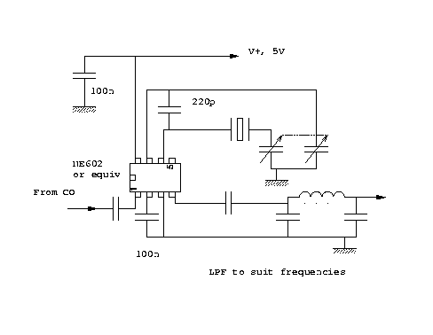
A `breadboard' was built up using an NE602 in
the cicuit below.

This test version used a 10MHz resonator, which is not recommended, for
reasons of stability, but since a 24MHz crystal, bought for 75p
at a rally was to hand, This provide coverage of 20m from below 13.990MHz
to 14.280 using a large airspaced variable, also bought at a rally,
and believed to be 365+365pF. The ouput network is a straight copy of
that used in the `Gremlin' TX (Sprat ??).
In principle one can use either additive or subtractive mixing. The latter leads to an intrinsically cleaner design as most of the spurii will be above the output frequency. Also a lowpass, rather than a bandpass filter can be used to clean the signal up.
Looking for common computer frequency crystals, all obtainable new for less than about £ 2.0, and keeping to resonators of 6MHz or less, the following all look possible. Experiments suggest that 4MHz resonators can be pulled reliably down by 100kHz and 6MHz by about 150kHz. (It is also easier to pull down than up, another advantage of subtractive mixing in this application.)